pn 16 means
v notch ball valve
spring loaded nrv
forged ball valve
What Is Positioner In The Control Valve?
A control valve positioner is an important accessory for most types of valves. The primary function it performs, about your system’s setpoint and flow rate, and pressure requirements. The controller system sends an input signal directly to the valve positioner and controls the actuator movement, through the actuator to control the valve opening. The positioner senses this exact movement and communicates with it for smooth operation. Due to THINKTANK with mass production of control valves, we also stock plenty of valve positioners at a cheaper price in the warehouse, if you are interested just feel free to contact our sales representative. [email protected]
Control Valve Positioner Working Principle
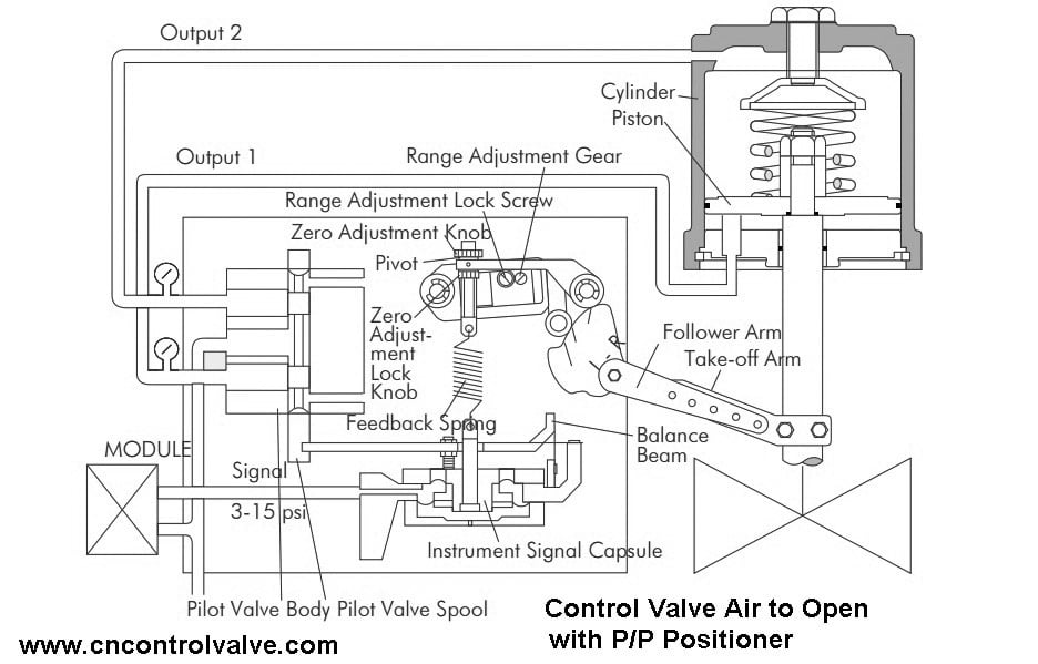
For mechanical Electro-Pneumatic valve positioner, accurately controls valve stroke in response to an input signal of 4-20mA from the controller. And for mechanical Pneumatic-Pneumatic valve positioner input signal is 3-15psi.
Above is the working principle for the E/P positioner which is used for diaphragm pneumatic actuated control valves, a sliding globe type control valves.
When the input signal is supplied to the positioner to open the valve, power is generated from ① the torque motor and pushes ② the flapper to the opposite side of ③ the nozzle. The gap between ③ the nozzle and ② the flapper becomes wider and from the inner part of ④ the pilot, air inside ⑨ the chamber is exhausted through ③ the nozzle. Due to this effect ⑤ the spool moves to the right. Then, ⑦ the seat which was blocked by ⑧ the poppet pushes
the poppet away and supplied pressure (air) goes through ⑦ the seat and OUT1 Port and enters into ⑩ the chamber of the actuator. Then ⑩ chamber’s pressure will increase and when there is enough pressure inside the chamber to push ⑪ the actuator’s spring, ⑫ actuator’s stem will start to go down and through the feedback lever, the stem’s linear motion will be converted to span ⑭ lever’s rotary motion. This ⑭ span lever’s rotary motion will then once again rotate ⑮ the span and pull the spring. When the valve’s position reaches the given input signal, ⑯ span spring’s pulling force and ① torque motor’s power will be balanced and move ② the flapper back to its original position to reduce the gap between ③ the nozzle. The amount of air being exhausted through ③ the nozzle will reduce and ⑨ the chamber pressure will increase again. ⑤ Spool will move back to its original position on the left and ⑧ the poppet will also move in the same direction blocking ⑦ the seat to stop the air coming into the ⑩ chamber through the supply. As a result, the actuator will stop operating and the positioner will return to its normal condition.
The calibration Method of Mechanical Electro Positioner in Pneumatic Control Valve
How is an E/P Valve Positioner Working For Rotary Type Control Valves?
When an input signal is supplied to the positioner to open the valve, power is generated from ① the torque motor and pushes ② the flapper to the opposite side of ③ the nozzle. The gap between ③ the nozzle and ② the flapper becomes wider and from the inner part of ④ the pilot, air inside ⑨ the chamber is exhausted through ③ the nozzle. Due to this effect ⑤the spool moves to the right. Then, ⑦ the seat which was blocked by the poppet pushes ⑧ the poppet away and supplied pressure (air) goes through ⑦ the seat and OUT1 Port and enters into ⑩ the chamber of the actuator through OUT1. Then ⑩chamber’s OUT1 pressure will increase and ⑪ the actuator’s stem will rotate and through ⑫ the feedback shaft, the actuator’s rotating motion will be transferred to ⑬ the cam. This motion will then rotate⑭ the span lever and pull ⑮ the span’s spring. Once it reaches the given input signal, ⑮span spring’s pulling force and ① torque motor’s power will be balanced and move ② the flapper back to its original position to reduce the gap between ③ the nozzle. The amount of air being exhausted through ③ the nozzle will reduce and ⑨ chamber pressure will increase again. ⑤ Spool will move back to its original position on the left and ⑧ the poppet will also move in the same direction blocking ⑦ the seat to stop the air coming into the ⑩ chamber through the supply. As a result, the actuator will stop operating and the positioner will return to its normal condition.
Control Valves 101: Valve Types, Applications, Components, and Accessories
How Many Types Of Valve Positioners For Control Valves?
Typical there are 3 types of valve positioners that are common to use in process control valves.
- Mechanical Electro-Pneumatic Valve Positioner (E/P Positioner)
- Mechanical Pneumatic-Pneumatic Valve Positioner (P/P Positioner)
- Digital Positioner, also called Smart Positioner
Smart Positioner V.S Normal Positioner
Why digital positioner is such important for control valves?
Normal positioners like Electro-pneumatic valve positioners convert precise electronic signals to an equivalent set of air pressure, and smart positioner uses a microprocessor to position the valve actuator while monitoring and recording data. It functions similarly to an analog-type positioner, E/P positioner, except that electronic signals are converted into digital for greater accuracy which results in less use of air when compared with older types on purely mechanical systems. Online diagnostics also allow operators easy access so problems can be found quickly.
Troubleshooting of Siemens SIPART PS2 Valve Positioner
What Are Analog I/P Valve Positioners?
Most modern processing equipment uses 4 to 20 mA DC signals when modulating control valves. This introduces electronic components into the positioner model. The positioner converts electronic current signals into pneumatic pressure signals. In a typical analog I/P Positioner, the converter receives a voltage input signal and provides a proportional pneumatic output signal over a nozzle-flapping scheme.
A Digital Valve Positioner receives an electric signal (typically 4-20mA, HART, PROFIBUS, or Foundation Fieldbus) from a controller. It then sends a corresponding pneumatic signal to a pneumatic valve actuator.
Digital valve positioners are electrical signal generators receiving a voltage signal from a controller. These signals typically range from 4-20A to PROFIBUS and Foundation Fieldbus. The actuator then receives a corresponding pneumatic signal via a valve. The electrical input of a digital positioner can be a digital signal, thus adding advanced capacity for the operator. The PS2 of Siemens allows remote management of all pneumatic devices. Our service supports a range of communication protocols and features that are compatible with all end-use users.
Pneumatic Positioners is a pneumatic signal (usually 3-15 PSIG) is supplied to the positioner. The positioner translates this to a required valve position and supplies the valve actuator with the required air pressure to move the valve to the correct position. For more information, you can contact THINKTANK’s representative.
A valve positioner is a device used to increase or decrease the air load pressure driving the actuator until the valve’s output to the control valve actuator’s input. Connect/reconnect the tubing and set the input signal to a mid-range value. valve is used to adjust a valve’s position based on the desired set point for a process variable, whether it be pressure, temperature, or flow.
Producers typically install positioners on the yolk or top casing of a pneumatic actuator for linear control valves. On rotary control valves, the valve positioner is installed in line with the valve and actuator stems on top of the actuator or the side of the actuator. Installation depends on what type of actuator one uses. Affixing the positioner to the actuators allows the positioner to measure the stem travel (linear valves) or valve until the valve’s stem reaches a position balanced to the output signal from the process variable instrument controller. Positioners are generally mounted on the side-yoke or top casing of the pneumatic actuator for linear-sliding-stem control valves and at or near the end-of-shaft for rotary control valves. For either basic design type, the valve positioner is connected mechanically to the valve stem or valve shaft so that its position can be compared with the position dictated by the controller.
Positioner Control Valve
A positioner control valve that is positioner for control valve is used to adjust a valve’s position based on the desired set point for a process variable, whether it be pressure, temperature, or flow. How does a positioner work? Producers typically install positioners on the yolk or top casing of a pneumatic actuator for linear control valves. Pneumatic Valve Positioner receives a pneumatic signal (typically 3-15 or 6-30 psi) from a controller. It then sends a corresponding pneumatic signal to a pneumatic valve actuator.
THINKTANK’s E series globe control valves can be used Fisher FIELDVUE DVC6200 Digital Valve Controller on a 657 or 667 diaphragm actuator, signal to a pneumatic valve actuator. Positioners are used on controlling valves where accurate and rapid control is required without error or hysteresis. Positioners are generally mounted on the side-yoke or top casing of the pneumatic actuator for linear sliding stem control valves, and at/near the end-of-shaft for rotary control valves. For either basic design type, the “mechanical feedback linkage” connected directly to the valve’s stem provides feedback to the controller. The process controller tells the positioner to “change” position. They require position feedback from the valve stem or shaft and deliver pneumatic pressure to the actuator to open and close the valve.
How Does A Positioner Work?
Manufacturers install typical valve positioners on the yolk or the upper casing for pneumatic actuator systems for linear control valves. On rotary control valves, the valve positioner is installed in line with the valve and actuator stem on top of the actuator or at the bottom of it. Installing the positioner to the actuators allows the positioners to measure stem distances (linear valves) or degrees of rotation (rotary valves). This also alters the desired direction of the position of one actuator. Whenever process variables have different values from the desired set of values, the instrument controllers send an electrical message to the positioner.
Valve Positioner Assembly Method
A linear positioner should be installed on control valves that use spring return diaphragm type or piston actuator to operate, especially for globe type control valves.
Before proceeding with the installation of the positioner, ensure the following components are available.
- Positioner
- Feedback lever and lever spring
- M6 nut and spring washer (fastening feedback lever to the main shaft)
- Bracket, bolts, and washers for positioner – not supplied with the positioner
- Connection bar – not supplied with the positioner
Note: Please make sure the bracket for the positioner is right for the yoke of control valves.
When you design the bracket you need to consider the following 2 points. (Most of you can ask the control valve supplier to provide the bracket, THINKTANK can help our customer to produce the bracket, tubing, and fitting accessories.
- The feedback lever of the positioner should be vertical to the valve stem at 50% of the valve stroke.
- The connection clamp between the valve stem and actuator stem for the feedback lever should be installed, the valve stroke should match the corresponding “mm” marked on the feedback lever. Because Improper setting may lead to poor linearity performance.
Installation of E/P Positioner For Globe Control Valves
Step 1: Assemble the positioner with the bracket made in the previous step by fastening the bolts (M8 * 1.25P).
Step 2: Attach the positioner with the bracket to the actuator yoke. Please kindly note don’t tight the bracket firstly, because later we are going to adjust the positioner.
Step 3: Connection bar install to the actuator clamp. The hole gap on the feedback lever is 6.5mm so the connection bar’s outer diameter should be less than 6mm.
Step 4: Install an air filter regulator to the actuator, and ensure the supply air coincides with the actuator required. Then supply enough air pressure to the actuator to make the valve stroke at 50% of the full stroke.
Step 5: Please make sure the connection bar is in the right place of the feedback lever and lever spring. Pay more attention to the blowing figure to ensure you are installation right. The left figure is right to insert position, the connection bar must be located upward from the lever spring.
Step 6: Make sure the feedback lever is vertical to the valve stem at 50% of the valve stroke. If it is not vertical, please adjust the bracket or connecting rod to make it vertical. Improper installation may cause poor linearity performance also.
Step 7: Double-check the valve stroke. The feedback lever has the stroke number on it, we need to position the connection rod at the number on the feedback lever which corresponds to the required valve stroke. If not in the right place, simply adjust the bracket, or move the connection rod.
Step 8: When we finished all the above 7 steps, start to operate the valve from 0% to 100% stroke of the control valve by using direct air to the actuator. Observing the linear lever stopper during valve opening from 0% to 100%, it should not touch the stopping bosses of the positioner, see above figure. If the linear lever stopper is touched, the positioner should be adjusted from the yoke.
Step 9: Congratulation, you have done the installation of the valve positioner, now let’s tighten all of the bolts or nuts on the bracket and the connection rod.
Final Thoughts:
In this post, we have introduced control valves with valve positioners, and there is more related knowledge about valve positioners and control valves we recommend you to read it.
The calibration Method of Mechanical Electro Positioner in Pneumatic Control Valve
What Is Positioner?
Introduction of Intelligent Positioner in Control Valves
What effect does the positioner cam have on the valve characteristic?
How does an electro-pneumatic positioner work?
THINKTANK is a professional and reliable supplier of control valves, if you have any questions about process control valves, welcome to send your message to us.