wedge gate valve
motorized control valve
automatic gate valve
butterfly gate valve
If you’re looking for tips on how to calibrate a control valve, you’ve come to the right place. In this blog post, we will discuss the importance of calibration and walk you through the steps needed to properly calibrate a control valve. By following these simple steps, you can ensure that your control valve is functioning at peak efficiency and delivering optimal performance in your industry process.
Calibrate a Control Valve without Valve Positioner
Diverse sequencing patterns may be assumed by split-ranged control valves. Complementary, exclusive, and progressive control valve sequencing methods are often used in the process sector.
Split-Range Control and Its Complements
With this type of split-ranging, there is never an output range state when both valves are completely open or closed. Instead, each valve enhances the function of the others. When base and pigment liquids are combined to create colorful paint, as seen below, two valves are often used to balance the combination of the two fluid streams. This is an example of complementary split-range control.
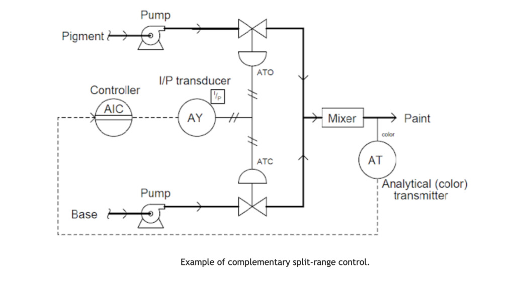
The same controller output signal drives the base and pigment valves. The base valve ATC means air to close, and the fail position is a valve to open(FO). whereas the pigment valve ATO means air to open, and the fail position is a valve to open(FC). The relationship between each control valve’s valve opening and the controller’s output is displayed in the following table:
| Controller Output (%) | l/P Output (PSI) | Pigment Valve (Stem position) | Base Valve (Stem position) |
| 0 | 3 | Fully Closed | Fully Open |
| 25 | 6 | 25% Open | 75% Open |
| 50 | 9 | Half-Open | Half – Open |
| 75 | 12 | 75% Open | 25% Open |
| 100 | 15 | Fully Open | Fully Closed |
Exclusive Split-Range Control
This kind of split-range control has a throttled route for process fluid that is “EITHER OR” by nature of the valve sequencing. In other words, process fluid never passes through both valves at once; it always passes through one or the other.
When using split-ranged control valves, it is necessary to sequence the valves so that both are completely closed at a 50% controller output signal, one valve fully opens as the controller output increases to 100%, and the other valve fully opens as the controller output decreases to 0%.
When reagents are fed into a pH neutralization process, where the pH value of the process liquid is raised by the addition of either acid or caustic, this type of split-ranging is used practically as follows:
The above procedure’s fundamental guiding principle is:
- A pH analyzer checks the mixture’s pH level, and a single pH controller tells two reagent valves when to open.
- The controller’s output signal rises as the process pH rises, opening the acid valve directly as a result (direct action).
- The pH level of the mixture will decrease as a result of the addition of acid.
- If the process pH starts to fall, on the other hand, the controller’s output signal will also drop, closing the acid valve and opening the caustic valve.
- The pH level of the mixture will increase as a result of the caustic addition.
The operating range of the Air-To-Open acid valve is 9 to 15 PSI, while that of the Air-To-Close caustic valve is 9 to 3 PSI. The relationship between each control valve’s valve opening and the controller’s output is displayed in the table below:
| Controller Output (%) | l/P Output (PSI) | Acid Valve (Stem position) | Caustic Valve (Stem position) |
| 0 | 3 | Fully Closed | Fully Open |
| 25 | 6 | Fully Closed | Half – Open |
| 50 | 9 | Fully Closed | Fully Closed |
| 75 | 12 | Half – Open | Fully Closed |
| 100 | 15 | Fully Open | Fully Closed |
Continually Split-Range Control
To increase the operating range of flow control for a particular fluid beyond what a single control valve could deliver, this type of split-range control for control valves is used. In this type of control, one of the valves, typically a small valve, gradually opens until it is fully open at 50% of the controller output while the large valve stays closed until the controller output exceeds 50% before it begins to open. When the controller output is 100%, both valves fully open.
A pH control process, where the incoming liquid always has a high pH value and must be neutralized with acid, is an illustration of progressive split-range control:
The analyzer, AT, measures the PH of the incoming water to be treated. The small acid valve begins to open as the controller AIC’s output rises and opens completely at 50% of controller output. The large acid valve will continue to be closed until the controller output reaches 50%. To guarantee that the PH of the incoming water is neutralized, the small and large acid valves are both fully open at 100%.
The following diagram illustrates the controller output and valve status necessary for small and large acid control valve sequencing:
| Controller Output (%) | l/P Output (PSI) | Small Acid Valve (Stem position) | Large Acid Valve (Stem position) |
| 0 | 3 | Fully Closed | Fully Closed |
| 25 | 6 | Half Open | Fully Closed |
| 50 | 9 | Fully Open | Fully Closed |
| 75 | 12 | Fully Open | Half Open |
| 100 | 15 | Fully Open | Fully Open |
Before each THINKTANK control valve leaves the factory, our engineers will complete the material tests, NDT tests, hydraulic tests, sealing tests, leakage tests, and function tests. However, due to the collision or displacement during transportation, the control valve should be debugged again after being installed on site.
Today we will talk about how to quickly debug the mechanical electro-positioner of the pneumatic diaphragm control valve.
Firstly, when the air source is connected, adjust the pressure gauge to the required pressure value of the actuator. For example, 0.2bar air supply of 40-200kpa spring diaphragm actuator, 2.4bar air supply of 80-240kpa spring range. Generally, the air source pressure of the diaphragm actuator cannot exceed 3.5 bar, otherwise, the diaphragm will be easy to be damaged.
7 Steps to Calibration of Control Valve Positioner
The Calibration Method of Mechanical Electro Positioner in Pneumatic Control Valve
Step 1: Check the Actuator Spring Range
This actuator spring range is 80-240kpa, so we first adjust the pressure regulator to 2.4bar.
Step 2: Connect Wiring
Open the function box of the valve positioner, and connect the analog signal’s positive and negative poles.
Step 3: Feedback Level Position
Open the positioner cover, adjust it manually to ensure the feedback rod is in the horizontal position when the valve is at 50% opening, and then fix the feedback rod clamp block.
Step 4: Calibrate the Zero Position
Calibrate the zero position. 0% travel length. This black wheel is the zero adjust knob. Set the input signal to 4 mA to see if the positioner output pressure is zero. If not, adjust the black knob to make the output pressure gauge drop to zero, indicating that the valve is in the initial position (If it is air to open, the valve should be in the closed position. If it is air to closed, at 4 mA, the valve should be in the fully open position). We can see that this valve is now in the closed position.
Step 5: Zero Adjustment
Input a 5 mA signal to see if the valve responds. If no feedback, adjust the zero adjust knob till the positioner output pressure gauge and valve start action. Back to 4 mA input signal to see if the valve is in the closed position. In other words to see if the positioner pressure gauge is in zero position. If it doesn’t back to zero, keep adjusting the knob till the pressure gauge is in zero adjustments. Input 5 mA signal again, and the valve starts response.
Step 6: Adjust the Travel Range
100% full travel position. Input 20 mA, whether the valve is at 100% opening. If the valve travel indicator is too low or too high, it is necessary to readjust the full position. Loosen the locking screw and adjust the travel lever. The + sign indicates an increase in travel. The – sign means to reduce travel length. If the valve does not reach 100% position after 20 mA is given, move the screw to + direction by 1 mm. Then tighten the locking screw. In particular, it is necessary to readjust the zero position after adjusting the 100% full range opening. Now input 4 mA signal and check whether the valve is 0. If not, repeat step 4 until the valve returns to zero. Give a 20 mA signal again to see if the valve is in the 100% travel position. If it is not in the full range position, adjust the locking screw position again.
Step 7: Proportional Travel for Each Signal
After adjusting the full range and zero position, input 4 mA, 8 mA, 12 mA, 16 mA, and 20 mA, in turn to see if the travel indicator needle corresponds to the 0%, 25%, 50%, 75%, and 100% positions of the travel plate. So far, the mechanical electrical positioner debugging is completed.
HEP15, HEP16, HEP Valve Positioner Manufacturer
| Series | HEP |
| Type | HEP15: Explosion-proof, HEP16: Intrinsically-safety, HEP17:Water-proof |
| Input signal | 4~20mA, 4~12, 12~20mA·DC |
| Output characteristics | Linear, equal percentage, quick-opening |
| Air supply | 140~500kPa |
| Air consumption | 4L/min (Air supply: 140kPa) |
| Flow capacity | Max.110L/min (Air supply:140kPa |
| Air connection | Rc1/4″, 1/4NPT, G1/4″ |
| Ambient temp. | -40~+60℃(Explosion Site),-40~+80℃(Standard Site) |
| Ambient humidity | 10%~90%RH |
| Stroke | 6~10, 10~100mm |
| Shell material | A-alloy |
| Shell construction | HEP15:Ex. Certification dⅡCT6, as per standard GB3836.1, GB3836.2; Protection class of shell: IP65, as per standard GB4208, HEP16: Ex. Certification iaⅡCT6 Gb, as per standard GB3836.1,GB3836.4; Protection class of shell:IP65, as per standard GB4208 |
| Wire connection | M20×1.5,1/2NPT, G1/2″ |
| Performance | Accuracy: Within ±1% FSDead band: Within 0.1% FS |
| Speed | 4mm/s(HA2D Pneumatic Actuator) |
| Weight | 3.5kg |
Final Thought
Now you have known the calibration method of the control valve mechanical positioner, next time we will talk about intelligent positioner and pneumatic-pneumatic positioner debugging methods, including calibrating to Siemens positioner, ABB positioner debugging, FISHER positioner calibration, Flowserve positioner calibrate, etc. THINKTANK is a professional control valve manufacturer in China, with CE, ISO9001-2015, ISO14001, and SIL3 safety function certificates. If you need technical support and a business quotation for your project, please feel free to contact us.